Code for the quadcopter can be found here.
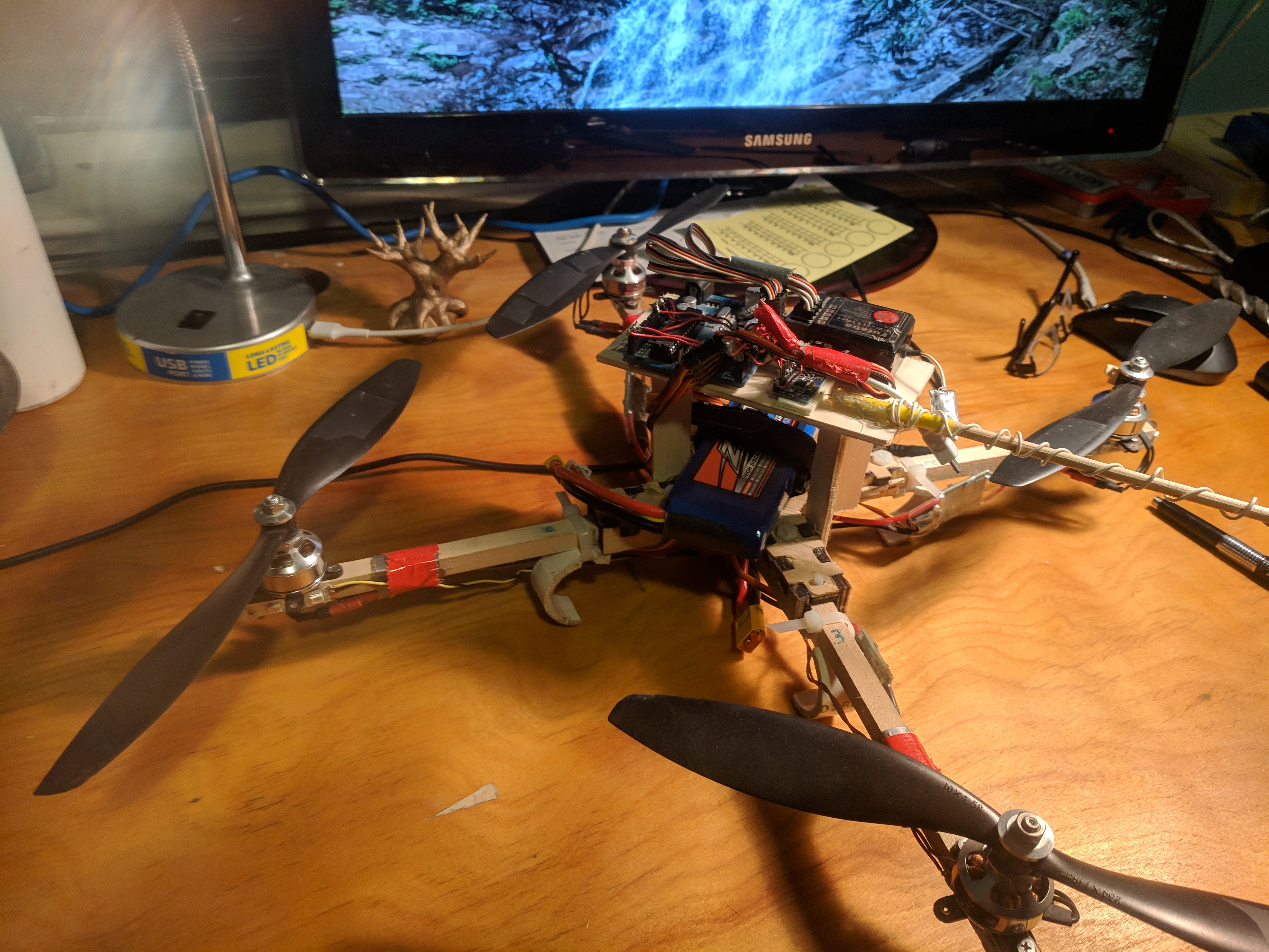
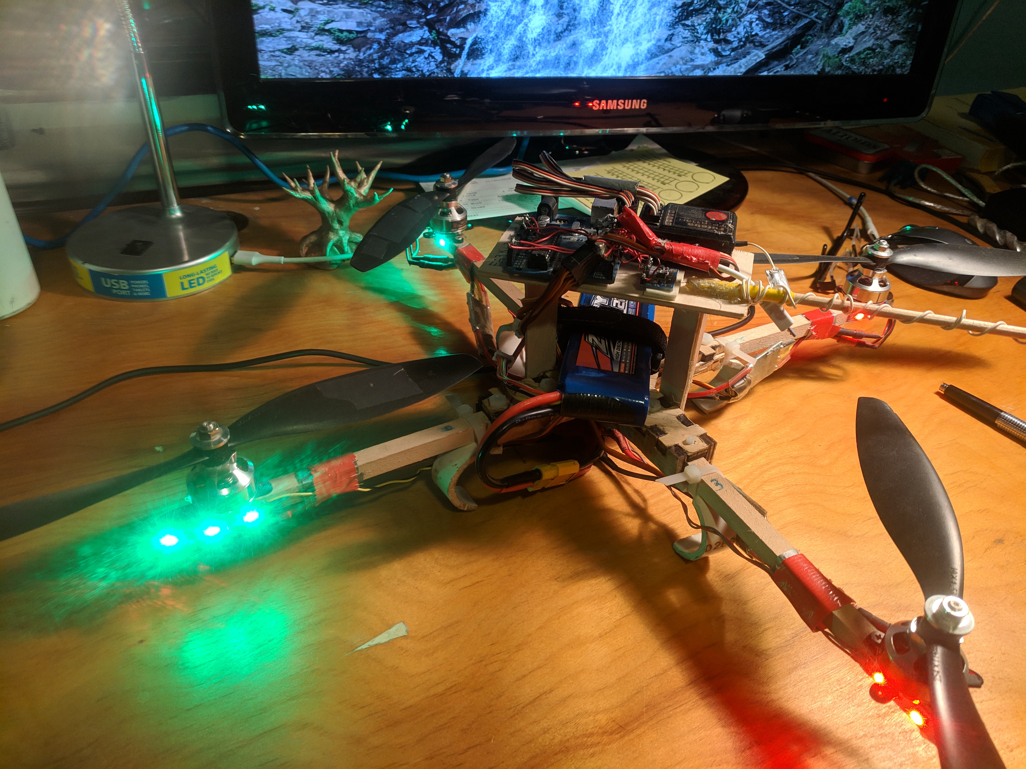
In 2014, when the quadcopter craze was kicking off, I really wanted a reasonably large quadcopter. I decided it would be a lot more fun (and cheap) to build a quadcopter from scratch. As I later realized, this was quite a task. I bought the cheapest brushless motors and speed controllers I could find on Hobbyking that were specced to turn 10 inch propellers and strapped them to a crappy plywood frame. With basically no control theory knowledge, the quadcopter did not fly at all. The hardware was also lacking. The frame was not nearly stiff enough and the motors were not very consistent.
I came to realize that there were four critical steps to building a functional quadcopter—good motors, a stiff, lightweight frame, properly implemented control loops, and accurate attitude data.
After doing some research, I found that my naive approach to PID control was doomed to failure. In order to control the pitch and roll of the quadcopter, I simply used the pitch and roll angles as the process variables and the thrust differential between the motors as the control variable. It turns out that pitch and roll angular velocities are much more appropriate control variables. To actually control the quadcopter's pitch and roll angles, I nested the angular velocity control loop inside of an angular position feedback loop. While this control scheme is mathematically identical to the original PID loops with an added double derivative (angular acceleration) term, the nested loops are easier to tune and handle conceptually.
A good feedback system needs to have fast and accurate feedback data. I used an MPU6050 accelerometer/gyro chip that I bought for a grand total of $2.99, and I got shockingly good data from such a cheap chip. The chip gives readings accurate to about five significant figures at 200 Hz, with a built in low pass filter. The main stumbling block for feedback was calculating the pitch and roll angles from angular velocity and accelerometer data. A really naive approach would be use the accelerometer to approximate which way is down. Accelerometer readings are generally noisy, especially when the accelerometer is mounted on a frame with four motors spinning at several thousand RPM. Even more critically, the accelerometer measures the sum of gravity and acceleration, so any movement of the quadcopter would confuse the accelerometer and the feedback systems. Another approach would be to integrate the gyroscope angular velocity readings, but this approach is also flawed. I originally found a library that implemented a Kalman filter that could run on the MPU6050 chip, but ultimately, I wrote my own Kalman filter that ran on the Arduino for increased control over the filtering process.
In order to tune the PID coefficients for the quadcopter, I wrote a Python program that simulated the quadcopter on one axis. I included simulated noise delays, and electrical characteristics of the motors in order to properly tune the quadcopter. Although I had to estimate the moment of inertia of the rotors and quadcopter, as well as the aerodynamic characteristics of the propellers, the PID coefficients from a well-tuned model worked fairly well in the real world.
The quadcopter is about as close to finished as it will ever be right now. However, I still have plans for improvement. I want to design a digital FPV system with a Raspberry Pi and a pair of Alfa AWUS036H WiFi adapters. With a barely legal 1 watt transmission power, I can get quite good signal strength pretty far away. I had attempted to run the FPV system with less powerful WiFi cards, but I ran into problems with the connection dropping and bad frames getting transmitted.